Steel Structural Installs
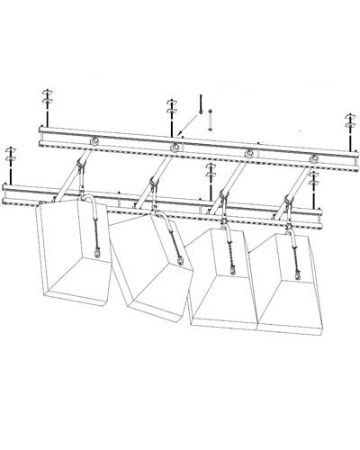
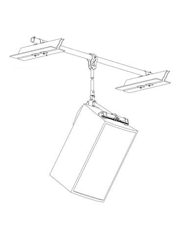
Scenario S1
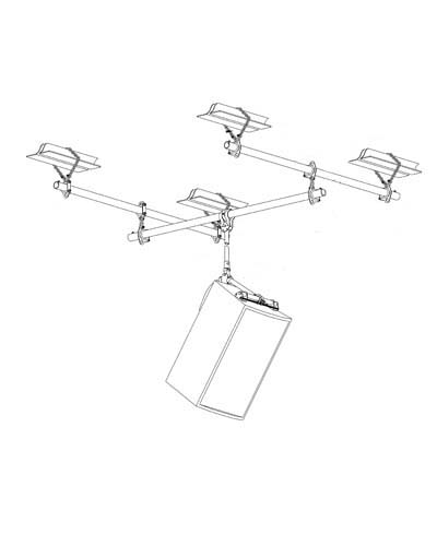
A rigging point is required between two structural members. A pipe beam will be used to span between the two members. Beam size required will vary with span and load. Consult a professional engineer if needed to determine proper size.
The APE Gimbal will accommodate pipe sizes thru 2″. Use steel pipe, SCH 40 or thicker.
Hardware required:
2 APE chain assemblies with shackles
2 APE pipe hangers with end stop bolts
1 length of steel pipe for beam, SCH 40 or thicker
1 length of 3/4″ steel pipe for stem, SCH 40
APE Hanger™ or CHAIN Monkey™ speaker rigging system
1 safety cable assembly. Hardware varies with application, see separate publication regarding safety cables.
Where a beam larger than 2″ pipe is required, add new beam, then refer to installation scenario(s) for rigging point at structural member. This structural connection can be made to either the top or bottom chord of truss where appropriate.
Chain assemblies can be used in basket, choker or endless basket configuration as shown.
Multiple speakers can be hung from the same beam or adjacent beams to form speaker array.
ALWAYS OBSERVE WORK LOAD LIMITS
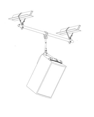
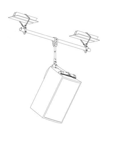
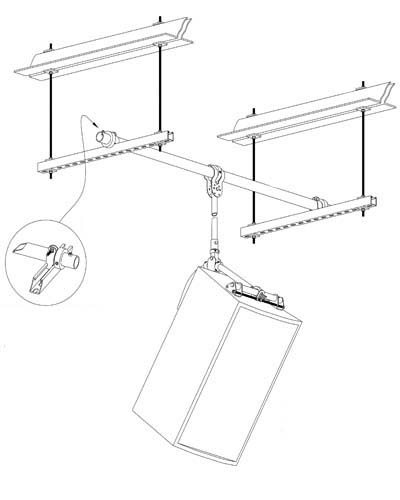
Scenario S2
A rigging point is required at a structural member. An obstruction exists at the exact location or, the location is where the ends of two joists bear on a common supporting member and a gap exists. A pipe beam will be used to span the obstruction or gap.
Beam size required will vary with span and load. Consult a professional engineer if needed to determine proper size. The APE Gimbal will accommodate pipe sizes thru 2. Use steel pipe, SCH 40 or thicker.
Hardware required:
2 APE chain assemblies with shackles
2 APE pipe hangers with end stop bolts
1 length of steel pipe for beam, SCH 40 or thicker
1 length of 3/4″ steel pipe for stem, SCH 40
APE Hanger™ or CHAIN Monkey™ speaker rigging system
1 safety cable assembly. Hardware varies with application, see separate publication regarding safety cables.
Chain assemblies can be used in basket or choker configuration.
Multiple speakers can be hung from the same beam or adjacent beams to form speaker array.
ALWAYS OBSERVE WORK LOAD LIMITS
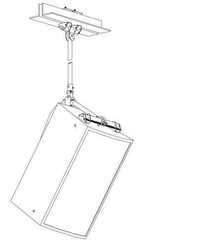
Scenario S3
A rigging point is required at a structural member, bottom chord of truss or similar configuration with gap at center. Our RAT™ 4-1 will be used to provide a connection point for our G5 or 06 Gimbal.
Hardware required:
1 RAT™ 4-1 (Rigging Attachment Technique 4-1) Refer to the RATS™ instruction manual for details.
1 length of 3/4″ schedule 40 steel pipe, ASTM A53 Grade A or better, if using our G5 Drill Guide/Gimbal.
1 APE Hanger™, U Tube™ or CHAIN Monkey™ speaker rigging system ordered with either the 05 or 06 Gimbal.
1 safety cable assembly. Hardware varies with application, see separate publication regarding safety cables.
ALWAYS OBSERVE WORK LOAD LIMITS
Scenario S4
A rigging point is required between two structural members. A pipe beam will be used to span between the two members. Beam size required will vary with span and load. Consult a professional engineer if needed to determine proper size.
The APE Gimbal will accommodate pipe sizes thru 2. Use steel pipe, SCH 40 or thicker.
Hardware required:
2 heavy duty, two hole, load rated pipe clamps
1 length of steel pipe for beam, SCH 40 or thicker
1 length of 3/4″ steel pipe for stem, SCH 40
APE Hanger™ or CHAIN Monkey™ speaker rigging system
1 safety cable assembly. Hardware varies with application, see separate publication regarding safety cables.
Where a beam larger than 2″ pipe is required, add new beam, then refer to installation scenario(s) for rigging point at structural member. Multiple speakers can be hung from the same beam or adjacent beams to form speaker array.
ALWAYS OBSERVE WORK LOAD LIMITS
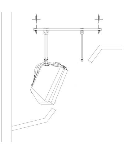
Scenario S5
Similar to scenario S1, except that a trapeze hanger will be used to span around an obstruction like ductwork or a conduit rack. Standard strut system hardware will be used such as Unistrut or B-Line. Observe the manufacturers beam loading data published in their catalog. Through bolt all connections and use lock washers at all connections (see note). Attach pipe beam to channel with APE Channel Interface. Beam size required will vary with span and load. Consult a professional engineer if needed to determine proper size.
The APE Gimbal will accommodate pipe sizes thru 2. Use steel pipe, SCH 40 or thicker.
Hardware required:
2 trapeze hangers. Hardware varies with application. Review manufacturers Strut System catalog for technical data and load tables.
1 length of steel pipe for beam, SCH 40 or thicker, and 2 APE Channel Interface
1 length of 3/4″ steel pipe for stem, SCH 40
APE Hanger™ or CHAIN Monkey™ speaker rigging system
1 safety cable assembly. Hardware varies with application, see separate publication regarding safety cables.
See scenario S6 for an expanded application of this technique.
ALWAYS OBSERVE WORK LOAD LIMITS
Scenario S6
This is an expanded application of the technique shown in Scenario S5. Please refer to Scenario S7 for an example of how this system can be used to overcome an installation challenge in a restrictive environment.
The APE Channel Interface provides a reliable connection between the pipe and channel while still allowing the pipe position to be safely adjusted.
The adjustment is made by loosening the clamp and rolling the pipe, with speaker attached, to the new position. This feature along with the ability to adjust the Gimbal’s position, using a push/pull clamp or mini chain puller, provides on-the-fly XY positioning of the speaker. We recommend using a compact electric chain hoist such as the CM Shopstar for hoisting speakers. Attach small web slings approx. 6″ to the side of the stem assembly, one around the pipe and one around the Axial Tube of the APE Hanger™. Insert hoist between these two points and lift speaker into position.
ALWAYS OBSERVE WORK LOAD LIMITS
Scenario S7
This is an example of how the system in scenario S6 can be used to overcome an installation challenge in a restrictive environment. Multiple speaker arrays must be installed inside a soffit above the proscenium. The installation must be accomplished thru a relatively small opening that will be grilled over after the install is complete. The soffit is constructed of light framing and does not provide a suitable work platform.
Taking advantage of the on-the-fly XY positioning of the system, the speakers are hoisted and hung within the grille opening and then slid back into position after making all necessary connections including signal cable. This is easily done using the swivel to rotate speaker.
ALWAYS OBSERVE WORK LOAD LIMITS
Scenario S8
This is a combination of scenarios SI and S2. A rigging point is required between two structural members but an obstruction exists at the exact location on the structural members.
Beam size required will vary with span and load. Consult a professional engineer if needed to determine proper size. The APE Gimbal will accommodate pipe sizes thru 2″. Use steel pipe, SCH 40 or thicker.
Hardware required:
- 4 APE chain assemblies with shackles
- 8 APE pipe hangers with end stop bolts
- 4 shackles
- 3 lengths of steel pipe for beams, SCH 40 or thicker
- 1 length of 3/4″ steel pipe for stem, SCH 40
- APE Hanger™ or CHAIN Monkey™ speaker rigging system
- 1 safety cable assembly. Hardware varies with application, see separate publication regarding safety cables.
Chain assemblies can be used in basket or choker configuration.
Multiple speakers can be hung from the same beam or adjacent beams to form speaker array.
ALWAYS OBSERVE WORK LOAD LIMITS
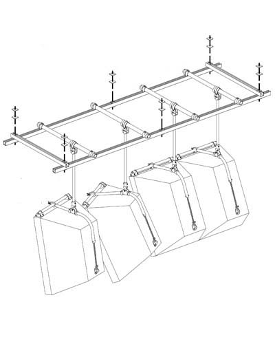
Scenario S9
This is a variation of Scenario S6. Please refer to Scenario S6 for additional details.
The channel spacing has been increased to 5′, a common spacing for steel structural members.
Although this variation requires a little more hardware, we consider it the superior method because of the added flexibility it offers. Using pairs of channels linked together with the Link Bolt Assemblies as shown, has the following benefits over Scenario S6:
- -A rough-in can be done prior to speaker installation with minimal hardware and without regard for placement of the pipes used to position the speakers. This is done by installing the upper channels using high strength internal suspension washers, threaded rods and the appropriate structural attachment hardware. Any lateral bracing that may be required can also be installed at this time.
- -Because the suspension rods do not extend below the upper channel, they are never in conflict with the pipes when positioning the speakers.
- -For the reason stated above, all speakers can be hoisted from one point if desired, then traverse the framework to the desired location. This is accomplished by adding and removing Link Bolt Assemblies. The technique allows the pipes, with speaker attached, to be rolled into position while maintaining adequate support of the lower channels that the pipes are connected to.
- -Proper placement of Link Bolt Assemblies allow both channels to share the load, increasing span capability. See “ref. 1” above.
REFER TO STRUT SYSTEM CATALOG FOR TECHNICAL DATA AND LOAD TABLES ALWAYS OBSERVE WORK LOAD LIMITS